Quick Answer
A large-diameter scrubber tower is not a scaled-up small tank. Once the shell reaches the large-diameter range — roughly two metres and above in common fabrication practice — it stops behaving like a stiff panel and starts behaving like a thin-walled ring: roundness, fit-up and weld sequence decide whether the tower goes together straight, and welding distortion can close a nozzle or put a flange face out of flat. The work therefore splits into two controlled stages. Flat panels are joined on a heated-tool butt welder while they are still flat, because the flat position allows machine-controlled temperature, pressure and alignment while keeping the seam accessible and efficient to produce. The rolled shell is then closed and assembled with extrusion welding, using alignment rings, a balanced weld sequence and dimensional checks after every course. Where applicable, use the EN 12573 series and/or the relevant DVS 2205 design rules together with the project specification. Weld PP to DVS 2207-11 and extrusion welds to DVS 2207-4, and verify roundness, plumb and seam quality before the tower leaves the shop.
Definition: What Counts as a Large-Diameter Structure
There is no universal diameter at which a scrubber becomes “large.” In fabrication practice, around 2,000 mm is a useful planning threshold because shells of this size increasingly require active support, roundness checks and controlled weld sequencing. The actual behaviour depends on diameter, wall thickness, material grade, temperature and stiffening arrangement. This guide uses that planning threshold, not a code limit: “large diameter” here means a tower where the shell must be actively supported and measured during assembly.
Why a Large Tower Behaves Differently
Three scaling effects explain most of the problems that appear only on large towers. They are worth understanding before the first sheet is cut, because each one changes a fabrication decision.
Ovality sensitivity increases rapidly with diameter. At the same wall thickness, a shell that can hold its shape easily at a small diameter may require alignment rings, distributed supports and controlled weld sequencing when the diameter becomes much larger. The actual stiffness depends on diameter, wall thickness, material properties, temperature, shell length and stiffening arrangement.
Thermal movement becomes a fit-up problem. Using an illustrative thermal expansion coefficient of 0.15 mm/m·K, a 12 m PP tower subjected to a 30°C temperature change could change length by approximately 54 mm. Actual expansion depends on the PP grade and temperature range, so the project should use the material supplier’s design data. That is enough movement to shift nozzle orientations, flange faces and anchor bolt positions if the tower is measured at one temperature and installed at another. Match-marking, slotted connections and temperature-compensated measurements are not optional refinements at this size; they are what keeps the tower installable.
The weld is no longer the stiffest part of the structure. On a small tank, a heavy weld bead can locally dominate a thin panel. On a large tower, the shell, stiffener rings and support structure carry the loads, and the weld’s job is to transfer stress without creating a notch. A convex bead with a sharp toe is a stress raiser; a flush or gently blended weld is not. This is the opposite instinct from “add more weld”.
The practical consequence is that large-tower quality is decided before welding starts: in the design, the segmentation, the rolling and the fit-up. Welding then either preserves that quality or destroys it.
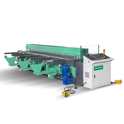
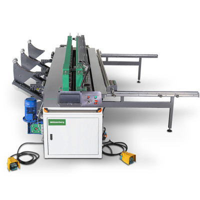
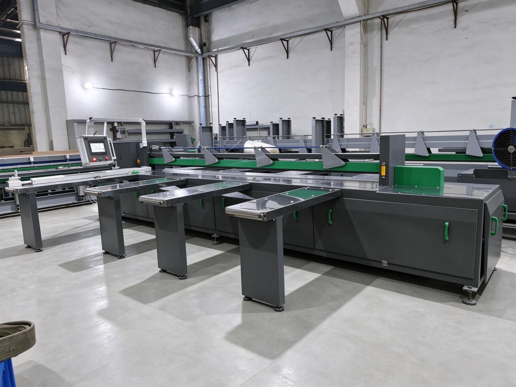
Flat panel prefabrication on a WeiBond butt welder keeps long seams accessible and allows temperature, pressure and alignment to be controlled before rolling.
Design Decisions That Set Up Every Weld
A scrubber tower is a vessel, a structure and a piece of process equipment at the same time. The design has to satisfy the chemical duty, the process internals and the loads — and every one of those decisions lands on the welder as a joint geometry or an access problem.
| Design decision | Why it matters at large diameter | What it changes in fabrication |
|---|
| Wall thickness and design factor | Hoop stress rises with diameter; long-term creep and chemical exposure reduce allowable stress | Sheet thickness, weld prep, number of passes, rolling effort and weight |
| Stiffener ring spacing | Controls ovality under wind, vacuum and handling loads | Whether rings are welded before or after shell seams; weld access and distortion |
| Support ring or leg arrangement | Concentrates the full tower load into a narrow band of shell | Local reinforcement, weld detail, inspection access at the most critical joint |
| Nozzle and manway positions | Openings interrupt load paths and create stress concentrations | Joint layout, reinforcement pads, whether the opening falls on a seam |
| Transport splits | Road width and weight limits cap shipped diameter and length | Flanged or field-welded joints, match-marking, trial assembly |
| Lifting points | A thin shell can buckle under a sling load | Lifting lugs, spreader beams, temporary stiffeners, lift plan |
Wall thickness and stiffness
Wall thickness is a design calculation, not a habit carried over from the last job. Where applicable, the EN 12573 series for welded static non-pressurised thermoplastic tanks and/or the relevant DVS 2205 design rules, together with the project specification, are the starting points for material-dependent stress and deflection checks. A scrubber is not always full of liquid in service, but it is often full during testing, and it carries wind, fan vibration and the weight of packing, mist eliminators and internal supports. Each of those loads has a different critical location. The shell may be governed by hoop stress at the bottom, by ring buckling under wind, or by local stress at the support ring — and the weld detail changes with the governing case.
For fabrication, the important output of the calculation is not a single number but a set of thicknesses: shell course by course, bottom knuckle, support band, nozzle reinforcement and stiffener section. Thick-to-thin transitions need a tapered transition rather than a step, and the weld at that transition needs a qualified procedure. A step change in stiffness is a stress raiser no weld can cure.
Stiffener rings and support
External stiffener rings are the cheapest way to keep a large shell round, but their welds are also a common source of distortion. A continuous fillet welded around a flexible shell pulls the shell inward as it cools. The usual sequence is to complete the main shell seams first, check roundness, then fit and weld stiffeners with a balanced pattern and enough cooling between segments. Where the ring crosses a longitudinal seam, the shell weld should be finished and inspected before the ring is closed over it.
Support rings deserve the same care. The entire tower load — shell, internals, liquid, wind moment — passes through a relatively narrow circumferential band. The shell in that band should be locally thicker or externally reinforced, and the weld should be a continuous, smooth transition rather than a series of short intermittent fillets. Intermittent welds can leave crevices where process liquid or contamination accumulates, increasing the risk of local chemical attack, deposits and difficult cleaning.
Nozzle and manway placement
Openings should not sit on a longitudinal seam. A seam under a nozzle is difficult to inspect, difficult to reinforce and almost impossible to repair without cutting out the nozzle. Keep a clear distance from seam centrelines; the minimum distance should be defined in the project specification and the qualified weld procedure, because it depends on wall thickness, nozzle size, reinforcement design and inspection access. Where an opening is large enough to remove a significant part of the shell section, the reinforcement pad or insert plate needs its own weld procedure and its own inspection.
Lifting and transport
A large empty tower is light for its size, which makes it easy to lift and easy to damage. Slings placed directly around an unsupported shell can ovalise it permanently. Lifting lugs should be welded to reinforced pads, or the load should be taken through a spreader beam and a temporary internal strongback. The lift plan belongs in the fabrication package, not in the crane operator’s head on the day.
Segmentation: Decide Where the Joints Go Before Cutting Sheet
Every large tower is a compromise between shop capability and transport reality. The question is not “can we build it in one piece?” but “which joints are better made in the shop, and which are better made on site?” A joint made in a controlled shop is usually cheaper, cleaner and easier to inspect. A joint made on site avoids a transport limit but adds weather, access and contamination risk.
| Build option | Best suited to | Advantages | Watch-outs |
|---|
| Full shop build, one piece | Diameters and lengths that fit normal road transport | All welds under shop control; one final dimensional check; no field welding | Transport permits, lifting loads, route restrictions |
| Shop-built courses, flanged splits | Tall towers with a manageable number of sections | Shop weld quality; fast site assembly; reversible joints | Flange flatness, gasket selection, bolt access, added weight and cost |
| Shop-built courses, field-welded splits | Towers too large for flanged joints or where a continuous shell is required | Continuous shell; no gasket creep; lower joint cost | Weather protection, field access, same procedure and inspection as shop |
| Full field fabrication | Very large or site-constrained projects | No transport limit | Lowest productivity; highest contamination and quality risk |
Three rules keep segmentation from creating problems later. First, put circumferential joints in low-stress zones, away from the support ring, the bottom knuckle and large openings. Second, keep longitudinal seams in adjacent courses staggered by the distance specified in the fabrication drawing, so the shell does not have a continuous line of weakness. Third, trial-assemble the sections in the shop, match-mark them and record the fit-up. Trial assembly in the shop greatly reduces the risk of fit-up problems on site and provides a reference for match-marking and dimensional checks. A tower that has never been trial-assembled can carry every tolerance error forward to the site, where access and correction are much more difficult.
- Joint locations clear of the support ring, knuckle and large nozzles
- Longitudinal seams staggered between courses
- Transport diameter and weight checked against the actual route
- Lifting points designed and marked before fabrication
- Trial assembly and match-marking completed in the shop
- Field joint procedure, access and inspection agreed before shipment
From Sheet to Shell: Cutting, Beveling and Rolling
The accuracy of the rolled shell begins with the cut panel. A panel that is out of square becomes a longitudinal seam with an uneven gap; an edge that is not freshly machined becomes a weld with contamination trapped in the fusion face. On a large tower those small errors are amplified by the circumference, so the cutting and edge preparation deserve the same attention as the welding.
Cut and bevel
CNC cutting gives repeatable panel dimensions and clean nozzle openings. The weld edges should be machined or planed after cutting, not left with a saw finish, and the bevel should be cut to the qualified joint design. For a double-sided extrusion weld, that usually means a V-groove with a small root face and a root gap that the procedure can tolerate. For a heated-tool butt weld, the joint faces must be parallel and square to the panel face; a tapered gap will not close evenly under the heating plate.
Roll with a template, not by eye
Roll the shell against a template or a set of radius gauges, and check the curvature at several points across the panel, not just at the ends. Thermoplastic sheet springs back after the rolls release, so the rolled radius is always larger than the machine setting. Over-roll slightly and allow the sheet to relax, then re-check. Rolling in several passes with small increments produces a more uniform curvature than a single heavy pass, and it puts less stress into the sheet.
Springback and ovality
A rolled course is never perfectly round when it comes off the rolls. Its own weight flattens it, the seam ends spring open and the diameter varies around the circumference. That is normal. What matters is that the course is measured and corrected before it is welded: support it at the correct points, bring the ends together with clamps, and check the diameter at four positions. If the course is already oval before welding, the circumferential seam will fight it, and the weld will either pull it further out or crack at the restraint.
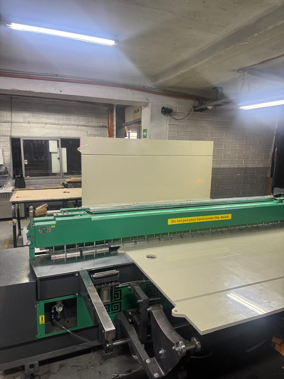
Accurate panel sizing and fresh, square weld edges reduce gap variation on the rolled shell.
Two Routes: Flat-First or Roll-First
There are two common ways to turn sheet into a shell, and they produce different weld quality and different risk.
| Route | Sequence | Best for | Main risk |
|---|
| Flat-first | Butt-weld panels into a full flat sheet, trim, bevel the closing edges, then roll and close the final seam | Thin to medium walls, large radii, shops with a wide butt welder | The butt welds are rolled with the sheet; weld reinforcement may need to be trimmed or removed where required by the qualified rolling and welding procedure, and the weld must tolerate the rolling operation |
| Roll-first | Roll each sheet or panel into an arc, then join the arcs with longitudinal extrusion welds | Thick walls, small radii, cases where welds must not be bent | More curved-position welding; ovality must be controlled during assembly |
| Hybrid | Butt-weld two or three panels flat, roll the combined panel, close the last seam in the curved position | Many large PP scrubber courses where both flat-panel butt welding and curved-position closing are practical | Requires both a butt welder and a qualified extrusion procedure |
For many large towers, the hybrid route can offer a practical compromise. It keeps the majority of the seam length on the butt welder, where the parameters are machine-controlled and the seam is flat and accessible, while limiting curved-position welding to the closing seam and the circumferential joints. The deciding factors are wall thickness and radius: the larger the radius and the thinner the wall, the more comfortably a butt weld can be rolled. For thick walls or tight radii, roll first and weld in the curved position.
Closing the Longitudinal Seam
The closing seam is the first place where the tower’s roundness is tested. The two edges have to meet with a controlled gap, no mismatch and no twist, and they have to stay that way while the weld cools. On a large shell, that is a fixturing problem before it is a welding problem.
Fit-up controls
| Feature | Control basis | Why it matters |
|---|
| Root gap | Within the range qualified by the welding procedure for the material and thickness | Too tight prevents fusion at the root; too wide needs excessive filler and increases shrinkage |
| Mismatch | Within the acceptance criteria of the project specification and the applicable DVS 2202 evaluation | Mismatch reduces the load-bearing section and creates a notch at the weld toe |
| Peaking | Flat across the seam within the project tolerance | A peaked seam is a hard spot that concentrates stress and resists roundness correction |
| Twist | Seam edges parallel along the full length | Twist closes the gap at one end and opens it at the other; the weld cannot compensate |
Weld sequence for a thick longitudinal seam
For thicker walls, the joint design and qualified welding procedure should determine whether a single-sided or double-sided weld is appropriate. Where a double-sided weld is specified, a typical sequence is a root pass from the outside, back-gouging or routing from the inside to sound material, and a second pass from the inside. The two passes should overlap in the thickness without leaving a void at the root. On a scrubber, the inside pass is also the one that matters for chemical resistance: a smooth, fully fused internal surface leaves no crevice for liquid to collect.
- Tack the seam at intervals defined by the qualified procedure, alternating sides and keeping tacks clear of the final weld path where the procedure requires removal.
- Weld the root pass with the qualified extrusion or hot-gas procedure, maintaining preheat and rod feed rate.
- Back-gouge the root from the inside to clean, sound material; do not leave a notch or a cold lap.
- Weld the inside pass, blending the toe into the parent sheet.
- Inspect before the seam is covered by the next course or stiffener.
Start and stop points
Do not start and stop all passes at the same location. Stagger the stops by a distance defined in the procedure and overlap the restart into the previous pass as specified. A line of start-stop points stacked in one place is a line of potential lack-of-fusion defects, and on a tall tower it will be at a different height on every course — which makes it easy to miss during inspection.
Circumferential Joints: Fit-Up Is the Whole Job
The circumferential seam between two courses is where ovality, out-of-square cutting and thermal movement all meet. If the two courses are not round to the same diameter, the weld has to close a gap that varies around the circumference; if the cut edges are not square, the gap closes on one side and opens on the other. No welding technique can fix either condition economically.
Bring the courses into line without welding to the shell
Use internal guide rings, external clamps and jacking lugs that are either temporary or welded to a removable pad. Welding temporary strongbacks directly to the shell creates weld marks that must be removed and inspected later, and the removal itself can gouge the surface. The better practice is to use friction clamps or bolted alignment rings that do not penetrate the shell.
Root access and backing
For a double-sided circumferential weld, the root pass is usually made from the outside, with access from inside for back-gouging and the second pass. Where the inside is inaccessible, a removable backing ring can support the root, but it must be removed or fully consumed; a permanent backing strip left in place creates a crevice on the process side. In chemical service, a crevice is a future leak path, not a convenience.
Weld in opposing quadrants
Divide the circumference into four quadrants and weld opposite quadrants in turn, rather than running continuously around the tower. This balances the shrinkage and keeps the shell from being pulled consistently in one direction. Allow each quadrant to cool before starting the next, and check the diameter after every quadrant on the first course. Once the sequence is proven, repeat it on every course so the distortion pattern is predictable.
Weld Sequence and Distortion Control
Distortion in a large thermoplastic shell is cumulative. Each weld pass shrinks locally; if the passes are all on one side, or all in one direction, the shrinkage adds up and the shell bends or ovalises. The cure is not a single technique but a sequence that keeps the shrinkage balanced.
- Balance sides and directions. Alternate inside and outside passes where the joint allows, and back-step long runs instead of welding continuously in one direction.
- Balance the sequence around the circumference. Divide long circumferential joints into opposing segments and sequence them according to the qualified fabrication plan so shrinkage is distributed around the shell rather than accumulated in one direction.
- Let it cool. Thermoplastics have low thermal conductivity; the weld zone stays hot long after the torch moves. Stacking passes without cooling builds heat and shrinkage. Use the procedure’s interpass temperature as a limit, not a target.
- Check after every course. Measure diameter and plumb before the next course is fitted. A correction made at the current level is cheap; a correction made three courses later is a rework project.
- Do not weld stiffeners to a distorted shell and expect them to straighten it. A stiffener welded to an oval shell locks the ovality in. Straighten first, then stiffen.
- Weld sequence written on the fabrication drawing, not left to the welder
- Opposite quadrants and back-step runs used on circumferential seams
- Interpass temperature checked with a contact thermometer
- Diameter and plumb measured after each course
- Stiffeners fitted only after the shell is round
- No forced alignment of flanges or nozzles after welding
Nozzles, Manways, Flanges and Stiffeners
These details are small compared with the shell, but they are where most service leaks and installation problems appear. The reason is geometric: a nozzle or a stiffener interrupts the smooth shell, creates a stiffness change and gives the weld a place to start a crack.
Openings
Nozzle necks should be a close fit in the shell opening, with the weld landing on a clean, flat surface. Where the shell is curved, the nozzle end should be contoured to the curvature rather than pulled into place with bolts. A nozzle that is forced to close a gap will distort the shell around it, and the flange face will not be flat after welding. Reinforcing pads should have rounded corners, not square ones, and should be continuously welded around the perimeter if the service is corrosive.
Flanges
Where the flange design and fabrication sequence allow, final facing after welding can compensate for distortion introduced during welding. Bolt-hole finishing should likewise follow the project fabrication procedure so the final pattern remains aligned with the mating flange. For large flanges, check flatness with a straight edge and feeler gauge at four positions, and record the result.
Stiffener rings
Stiffener rings are structural, but their welds are also exposed to the process atmosphere on the inside if the ring is internal. Internal rings should be continuously welded and sealed, with no open crevices behind the ring. External rings can be intermittent only if the service is dry and non-corrosive; for a scrubber, continuous fillet welds with rounded toes are the safer default. Where a ring crosses a shell seam, the shell seam should be completed and inspected first, then the ring fitted over it with a good fit.
Access, Safety and Working Inside the Tower
A large tower may qualify as a confined space depending on its access, ventilation, intended occupancy and the applicable site regulations. Before internal welding begins, the fabrication team should assess the space under the site’s confined-space entry procedure, because welding inside it combines three hazards: fume, heat and restricted escape. The fabrication plan has to address all three before the first weld is made inside the shell.
- Ventilation. Use local extraction at the weld head and general ventilation through the shell. PVC welding can release hydrogen chloride; PP and PVDF fumes are also not safe to breathe. Do not rely on the manway as the only opening.
- Confined space entry. Treat the tower as a confined space whenever there is only one access point or the ventilation is not proven. Use a permit, a standby person outside, gas monitoring where the process atmosphere could be present, and a rescue plan.
- Hot work. Treat thermoplastic welding as hot work where required by the site’s safety rules and permit system. Keep combustible materials away from the work area and follow the project’s fire-watch requirements.
- Access and egress. Internal scaffolding should be independent of the shell where possible, with a clear route to the manway. Do not block the opening with welding equipment or cable.
- Manual handling. Sheet panels are large and flexible; use lifting equipment, rollers and suction lifts rather than manual carrying. A large PP panel is light but awkward, and a dropped panel can damage the shell or a person.
Dimensional Checks That Predict Problems
Dimensional inspection is not a final formality. On a large tower it is the feedback loop that tells you whether the weld sequence is working. Measure after every course, record the results and compare them with the previous course. A trend is more useful than a single pass/fail number.
| Check | Method | Typical target | What it predicts |
|---|
| Roundness / ovality | Diameter measurement at 0°, 90°, 180° and 270° on each course | Project-specific tolerance; the drawing or specification should state it | Fit-up problems at the next circumferential seam; difficulty installing internals |
| Plumb | Laser or plumb line from top to bottom reference | Project-specific tolerance; the drawing or specification should state it | Foundation misalignment; uneven load on anchor bolts; nozzle misalignment |
| Circumference and height | Steel tape at constant tension, corrected for temperature | Within the drawing tolerance | Course-to-course fit; total height; flange elevations |
| Weld mismatch | Straight edge and feeler gauge across the joint | Acceptance criteria of the project specification and DVS 2202 evaluation | Stress concentration and reduced section at the weld |
| Peaking | Straight edge across the longitudinal seam | Flat within project tolerance | Hard spot; difficulty holding roundness; coating or lining problems |
| Flange flatness | Straight edge and feeler gauge at four positions | Per flange standard or project specification | Gasket leakage; bolt preload loss; pipe alignment stress |
Temperature matters when you measure. A steel tape and a thermoplastic shell both expand, and a 12 m PP tower can change length by tens of millimetres over a working day, depending on the temperature swing and the material grade. Record the shell temperature with the measurement and correct to a reference temperature if the tolerance is tight. If the shop and the site are at different temperatures, agree on which condition the dimensions apply to before fabrication starts.
Testing Large Welds
Testing follows the same logic as the fabrication: check early, check in layers, and do not rely on one final test to find every defect. A large tower is difficult to test completely at the end, because access to the inside is restricted and a full water fill may not be possible on the site foundation.
- Visual inspection of every seam. Check bead shape, fusion, toe blending, surface defects and contamination. Evaluate heated-tool butt welds against DVS 2202 Supplement 1 and extrusion welds against DVS 2202 Supplement 5.
- Dimensional inspection. Roundness, plumb, mismatch and flange flatness as described above. A dimensionally out-of-tolerance tower is a quality problem even if every weld is sound.
- Weld qualification coupons. Weld test pieces with the same procedure, material and thickness, and examine them by macro-section and mechanical test where the project requires it. The DVS 2203 series covers testing of welded thermoplastic joints.
- Spark testing. Where applicable, electrical high-voltage testing in accordance with DVS 2206-4 can be used to detect through-thickness pores or cracks. The current guideline applies to welds up to 30 mm wall thickness and does not apply to electrically conductive or dissipative plastics. It complements rather than replaces leak testing or weld assessment.
- Water-fill or leak testing. Fill the tower or the liquid-tight sections in stages, hold and inspect every seam (DVS 2206-2). Check the foundation capacity first: a 12 m tower full of water can weigh far more than the operating condition, and the test can damage the foundation or the support ring if it was not designed for it.
- Documentation. Record material batch, welder, procedure, machine parameters, inspection results and test results. On a chemical plant project, this record is often a contractual requirement, and it is the only way to investigate a problem years later.
Field Assembly and Site Welding
Field work is not shop work with a longer walk. The wind, the temperature, the humidity and the access are all worse, and the inspection is harder. The way to keep field quality close to shop quality is to bring the shop with you: the same qualified welding procedure, the same fit-up criteria and the same inspection plan. Machine parameters should remain within the qualified range and be adjusted where the procedure allows for actual field conditions such as ambient temperature and wind.
- Shelter the joint. Wind removes the hot air from an extrusion weld and cools the seam unevenly. Erect a temporary shelter around the joint and check the ambient temperature before starting.
- Keep the joint dry and clean. Moisture and dust are the two most common causes of porosity in field extrusion welds. Wipe the joint, keep the rod in a sealed container and do not weld in rain or heavy condensation.
- Re-check the match marks. Field assembly should follow the shop trial assembly. If the marks do not line up, stop and find out why before forcing the joint.
- Use the same weld sequence. The field crew should work from the same sequence drawing as the shop, with the same quadrant order and the same start-stop stagger.
- Inspect before closing. Once a field joint is welded and the next section is lowered into place, the inside may be inaccessible. Inspect and record before the lift.
- Allow for movement. Anchor bolts, pipe connections and flange joints should be designed to accommodate the thermal movement of the tower, not force it into alignment.
Illustrative Build: 2.8 m × 12 m PP Scrubber
The following sequence is an illustrative example, not a universal specification. Dimensions, thicknesses and tests must come from the project design and the qualified welding procedure.
- Design and segmentation. A 2,800 mm internal diameter, 12,000 mm tall PP-H tower with a 12 mm shell, split into four 3,000 mm courses. The top two courses are flanged for transport; the lower two are shop-welded into one section. A support ring is located 500 mm above the bottom tangent line.
- Panel prefabrication. Each course is assembled from three flat panels, butt-welded on a 3,000 mm-capacity machine into a flat sheet with a circumference allowance. The panel edges are machined, the closing edges are beveled, and the weld reinforcement is trimmed flush before rolling.
- Rolling. Each panel is rolled against a radius template in several passes, allowed to spring back, and checked at four positions. The closing edges are brought together with clamps and the root gap is checked around the full circumference.
- Longitudinal seam. The closing seam is welded from the outside, back-gouged from the inside and welded again. The seam is inspected and the course is measured for roundness before the next step.
- Circumferential seams. The courses are stacked on alignment rings, matched for diameter and plumb, and welded in opposing quadrants. The root is welded from the outside, back-gouged and welded from the inside. Diameter and plumb are measured after each course.
- Nozzles and flanges. Nozzle openings are cut with a CNC router, the nozzle necks are contoured to the shell, and the fillet welds are made with extrusion welding. Flange faces are machined after welding and bolt holes are drilled to the mating pattern.
- Stiffeners and supports. External stiffener rings are fitted after the shell is round, welded with a balanced sequence and checked for distortion. The support ring is continuously welded and inspected.
- Testing and preparation for shipment. Visual inspection, dimensional check, spark test where specified, and a staged water fill of the lower section if the foundation is designed for it. The sections are match-marked, the flange faces protected and the openings sealed for transport.
The point of the example is not the dimensions. It is the order: design the joints before cutting, make the flat seams on the machine, roll to a template, fit the circumferential joints with alignment rings, weld in a balanced sequence, and measure after every stage. Every one of those steps is cheaper than correcting the step before it.
Common Defects and Their Root Causes
| Defect | Where it appears | Root cause | Prevention |
|---|
| Ovality after rolling | Whole course | Springback, single-pass rolling, unsupported storage | Over-roll and relax; roll in increments; store on saddles |
| Peaking at longitudinal seam | Along the closing seam | Excessive local heat, tight clamps, weld shrinkage | Balanced passes; check straight edge; do not force the edges |
| Mismatch at circumferential seam | Course-to-course joint | Out-of-round courses, out-of-square cuts, poor alignment | Measure each course; use alignment rings; trim before fitting |
| Cracks at weld toe | Stiffener and nozzle welds | Sharp notch, rapid cooling, high restraint | Blend the toe; preheat per procedure; restore shell roundness and correct fit-up before welding |
| Porosity in extrusion weld | Field and shop seams | Moisture, dust, oil, wrong rod temperature or feed rate | Clean and dry joint; sealed rod storage; qualified parameters |
| Leak at root | Double-sided seams | Incomplete fusion, gap too tight, back-gouge not deep enough | Control root gap; gouge to sound material; inspect before the second pass |
| Flange out of flat | Nozzle and manway flanges | Welding heat, flange faced before welding, forced fit-up | Face after welding; support the flange; check with a straight edge |
| Nozzle misalignment | Shell openings | Shrinkage, poor layout, no match-marking | Cut after shell is round; use templates; check orientation before welding |
Equipment Setup for Large-Diameter Work
The equipment list for a large tower is different from a small tank shop. You need a way to make long flat seams, a way to cut and bevel accurately, a way to roll and support the shell, and a way to weld in curved and overhead positions. No single machine does all four well.
| Equipment | Role in large-tower fabrication | Why it matters |
|---|
| WeiBond 3000 / 4000 butt welder | Flat panel prefabrication: joining sheets into full courses | Up to 3,000/4,000 mm welding width and 40 mm thickness; machine-controlled temperature and pressure for long, repeatable seams |
| EasyCut 3000 / 4000 | Cutting and sizing panels and nozzle openings | Clean, square edges reduce gap variation and fit-up time |
| WeiForm Pro | Bending and roll-forming knuckles, flanges, transitions and small-radius components | Combines welding and bending for details that are awkward on a plate roll |
| Weldy EX2 extrusion welder | Closing seams, circumferential joints, nozzle fillets, stiffeners and repairs | Up to 2.5 kg/h maximum output and 3–4 mm rod capability for the weld volume a large tower needs |
| Plate rolling machine | Forming the main shell courses | Large-radius rolling is a dedicated operation; the sheet line bender is not a substitute |
| Alignment rings and clamps | Holding courses round and aligned during fit-up | Prevents forced fit-up and the distortion that follows |
The machine settings for each joint should come from a qualified procedure, not from the display’s last job. Record the settings on the fabrication drawing and keep them with the inspection record. For a multi-course tower, that record is also the fastest way to diagnose a problem: if one course is out of round and the others are not, the parameter record usually shows why.
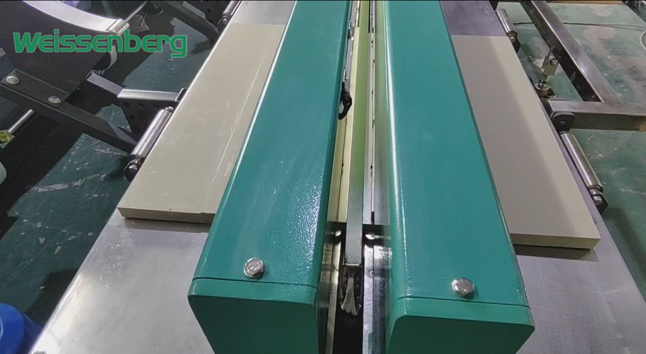
A wide butt welder keeps long panel seams flat and machine-controlled before the shell is rolled.
Frequently Asked Questions
What diameter counts as a large scrubber tower?
There is no official threshold. In fabrication practice, around 2,000 mm is a useful planning threshold, because shells of this size increasingly need active support, roundness checks and controlled weld sequencing. The actual behaviour depends on diameter, wall thickness, material grade, temperature and stiffening arrangement. A small tower can still need careful sequencing; a large one always does.
Can a 4 m diameter tower be built in one piece?
It can be built in one piece in the shop, but it usually cannot be shipped in one piece. Road width, weight and route restrictions vary by country and by route, so the permissible shipped diameter and length must be checked for the actual project. The usual answer is shop-built courses with flanged or field-welded splits.
Should the longitudinal seam be butt welded or extrusion welded?
Both are used, for different reasons. Butt welding is best for flat panel prefabrication because it is fast, machine-controlled and produces a homogeneous joint without filler. Extrusion welding is best for the closing seam of a rolled shell, circumferential joints, nozzles, stiffeners and repairs, because it works in curved and awkward positions. A hybrid route uses both.
How do you stop a rolled shell from going oval?
Roll against a template, over-roll slightly and allow springback, support the course at the correct points, and bring the closing edges together with clamps rather than force. Check the diameter at four positions before welding, and fit stiffener rings only after the shell is round. If the course is oval before welding, the weld will make it worse.
What wall thickness does a 2.8 m PP scrubber need?
That is a design calculation, not a rule of thumb. It depends on height, liquid level, wind and seismic loads, support arrangement, temperature and the long-term creep behaviour of the specific PP grade. The 12 mm in the illustrative example is only an example; the actual thickness must come from the project design and the material supplier’s data.
Do PP welds need stress relief after welding?
Routine stress relief of a large PP tower is not standard practice, and heating a finished shell can introduce more distortion than it removes. Distortion is controlled by weld sequence, fit-up and cooling, not by a post-weld heat treatment. If a project specifies annealing, it must be done to a qualified procedure with the shell supported and constrained.
How do you test a 12 m tower that cannot be filled with water?
Use the layered approach: visual inspection of every seam, dimensional checks, weld qualification coupons, spark testing where specified, and water-fill testing of the sections that can be safely filled. For the upper sections, rely on procedure qualification, in-process inspection and any additional non-destructive testing the project specifies. Document every layer.
Can field welds match shop weld quality?
Yes, if the field work uses the same qualified welding procedure and approved parameter range, the same fit-up criteria and the same inspection plan. The difference is environment: wind, moisture, temperature and access. Shelter the joint, keep it clean and dry, and inspect before the joint becomes inaccessible. Field quality fails when field work is treated as an exception to the shop procedure.
Key Takeaways
- A large scrubber tower is a thin-walled ring, not a scaled-up tank; roundness and fit-up decide the result.
- Join flat panels on a butt welder while they are flat, then roll and close the shell with a qualified extrusion procedure.
- Design the segmentation before cutting sheet: joint locations, transport splits and lifting points are weld decisions.
- Roll to a template, allow for springback, and measure the course before welding it.
- Fit circumferential joints with alignment rings, not by forcing the shell into place.
- Weld in opposing quadrants and back-step long runs; check diameter and plumb after every course.
- Face flanges after welding and drill bolt holes to the mating pattern.
- Test in layers: visual, dimensional, coupons, spark where specified, and staged water fill where the foundation allows.
- Treat every tolerance as a project-specific value defined by the design, the project specification and the qualified welding procedure — not a millimetre figure carried over from another tower.
References and Further Reading
Related Weissenberg Guides
Standards and Reference Sources
- DVS Regelwerk — DVS 2207 series: welding of thermoplastics, including heated-element welding of PP pipes, piping parts and panels (DVS 2207-11) and extrusion welding of pipes, piping parts and panels (DVS 2207-4).
- DVS 2205 series: design calculations for containers and apparatus made from thermoplastics.
- EN 12573: welded static non-pressurised thermoplastic tanks — general principles, design and calculation.
- DVS 2202: imperfections in thermoplastic welded joints — evaluation criteria; Supplement 1 for heated-tool butt welds and Supplement 5 for hot-gas extrusion welds.
- DVS 2203: testing of welded joints of thermoplastics — mechanical and macro-section tests.
- DVS 2206: non-destructive testing — including water-fill/leak testing (DVS 2206-2) and electrical high-voltage testing for through-thickness pores or cracks (DVS 2206-4, up to 30 mm wall thickness; not for electrically conductive or dissipative plastics).
Need help sizing a machine for a large-diameter tower? Send Weissenberg the shell diameter, course height, wall thickness and joint layout; the engineering team can match the butt welder, extrusion welder and handling setup to the fabrication sequence.