PVDF Sheet Butt Welding for Semiconductor Equipment: Achieving Leak-Proof Welds
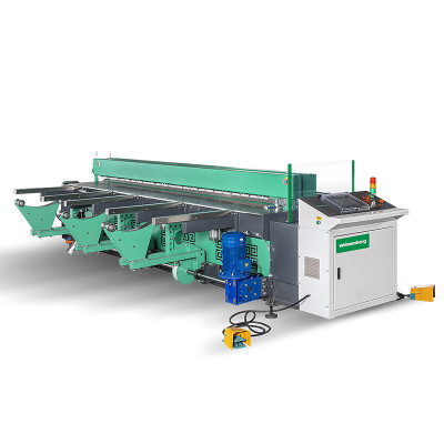
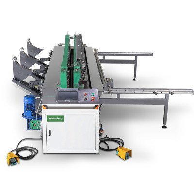
Key Takeaway: PVDF is the preferred thermoplastic for semiconductor wet process equipment due to its exceptional chemical resistance and ultra-high purity. Achieving leak-proof welds for semiconductor applications requires a systematic approach: particle control strategies, full material traceability, clean room discipline, and quality verification protocols that meet the stringent demands of semiconductor fabs. Process control and operator qualification form the foundation of reliable weld quality. Equipment that provides precise temperature control and data recording supports these process controls — Weissenberg's WeiBond series is one example of a machine platform designed for this purpose.
What Is PVDF and Why Does It Matter for Semiconductor Fabrication?
PVDF (polyvinylidene fluoride) is a high-performance, semi-crystalline fluoropolymer with the chemical formula (CH₂CF₂)n. It is widely specified in semiconductor, pharmaceutical, and chemical processing industries because of three defining properties:
- • Chemical inertness: Resists aggressive chemicals including concentrated acids, halogens, and organic solvents at elevated temperatures
- • Ultra-high purity: Minimal ionic extractables prevent contamination of high-purity process chemicals and rinse water
- • Thermal stability: Continuous service temperature range of –40°C to 150°C, with short-term peaks up to 170°C
In semiconductor fabs, PVDF is used for wet benches, chemical distribution systems, high-purity piping, tank linings, and process bath construction where any weld defect could compromise batch yield.
PVDF Welding Challenges for Semiconductor Applications
PVDF presents distinct welding challenges that set it apart from commodity thermoplastics like PP and HDPE. In semiconductor applications, these challenges are amplified by purity and cleanliness requirements.
Narrow Temperature Window
PVDF has a melting range of approximately 170–180°C depending on the grade (homopolymer vs copolymer). The recommended heating plate temperature for butt welding is 240–260°C — a narrower window than PP (190–210°C) or HDPE (200–220°C). Too low, and the weld interface will not melt sufficiently; too high, and thermal degradation produces bubbles and brittle joints that can shed particles into the process stream.
Surface Moisture Sensitivity
PVDF may absorb minimal surface moisture during storage. If not removed before welding, this moisture can vaporize and create porosity in the weld zone. Always follow the material supplier's recommended drying procedure. Additionally, PVDF has a higher coefficient of thermal expansion than PP, making fixture alignment and controlled cooling more critical for dimensional accuracy in precision semiconductor components.
Contamination Risk
Semiconductor-grade PVDF fabrication must prevent particle generation, ionic contamination, and organic residue introduction. Welding equipment, tools, and the surrounding environment must be controlled to avoid compromising the material's purity.
Weld Integrity Requirements
Leak-proof welds for chemical containment applications in semiconductor fabs require weld factors (ratio of weld strength to parent material strength) of 0.8 or higher per DVS 2207-1. For detailed DVS 2207 pressure profiles, heating times, and acceptance criteria, refer to our complete DVS 2207 compliance guide.
Required Equipment for PVDF Butt Welding
| Equipment | Required Specification for PVDF | Weissenberg Solution |
|---|---|---|
| Butt welding machine | Precise temperature control ±3°C; programmable pressure stages with data logging | WeiBond 3000 / 4000 / 6000 with PVDF recipe preset |
| Heating plate | Anti-adhesive coating (PTFE or ceramic); temperature range 240–260°C; uniform surface temperature | Standard equipment on all WeiBond models |
| Clamping system | Parallel clamping with gap tolerance ≤1.0 mm for sheets up to 1500 mm width | WeiBond hydraulic clamping |
| Edge planer | Clean, burr-free facing of PVDF edges immediately before welding | Integrated facing tool |
| Cleaning station | Isopropyl alcohol (IPA) or approved evaporating cleaner; lint-free wipes | — |
| Data logger | Records temperature, pressure, and cycle times per weld for traceability | Optional on WeiBond series |
Machine Selection Guide for PVDF Fabrication
Small-Scale / R&D
- • Recommended: WeiBond 1500
- • Sheet thickness: 3–15 mm
- • Max sheet width: 1500 mm
- • Manual pressure control
- • Ideal for: Lab equipment, prototype fabrication
Medium Production
- • Recommended: WeiBond 3000
- • Sheet thickness: 5–30 mm
- • Max sheet width: 3000 mm
- • Semi-automatic PLC control
- • Ideal for: Semiconductor wet bench fabrication
Large-Scale / High-Volume
- • Recommended: WeiBond 4000 / 6000
- • Sheet thickness: 5–50 mm
- • Max sheet width: 4000–6000 mm
- • Full automatic CNC + data logging
- • Ideal for: Chemical distribution systems, large tanks
PVDF Welding Parameters Overview
The table below summarizes the key parameters for PVDF butt welding as a starting reference. For detailed pressure profiles (alignment, heating-up, joining, cooling), heating times by sheet thickness, and DVS 2207-1 compliant parameter tables, please refer to our DVS 2207 standard compliance guide, which covers the full parameter specification for PVDF and other thermoplastics.
| Parameter | PVDF Range | Notes |
|---|---|---|
| Heating plate temperature | 240–260°C | Start at 250°C for standard PVDF-H; verify at plate surface with contact thermometer |
| Alignment pressure | 0.10 ± 0.01 N/mm² | Applied until initial bead forms |
| Heating-up pressure | ≤ 0.01 N/mm² | Reduced pressure during heating phase |
| Heating time | Per sheet thickness | See DVS 2207-1 Table 2 for precise values by material and thickness |
| Cooling time under pressure | Per sheet thickness | See DVS 2207-1; verify machine's PVDF recipe preset |
Important: Always perform trial welds under actual production conditions and adjust parameters based on the material certificate and applicable DVS standard edition. For the complete PVDF welding procedure including changeover times, pressure build-up times, and gap tolerances, consult DVS 2207-1 full parameter tables.
Clean Room and Environmental Controls
Semiconductor applications demand that the fabrication process itself does not contaminate the product. The required clean room grade depends on the specific semiconductor customer or project specification — always confirm the applicable class before planning production.
Environmental Controls
- • Perform welding in the clean room grade specified by the semiconductor customer or project specification (which may require ISO Class 5–7, depending on the customer specification)
- • Control temperature (20–25°C) and relative humidity (<50%) to minimize electrostatic charge on PVDF surfaces
- • Use HEPA- or ULPA-filtered positive pressure to prevent particulate ingress
Equipment Cleanliness
- • Wipe all machine surfaces contacting PVDF with IPA before each welding session
- • Inspect and replace heating plate anti-adhesive coating if any degradation is visible — degraded coatings can shed particles
- • Use dedicated clamping jaws for PVDF to avoid cross-contamination from other materials
- • All tools entering the clean area must be pre-cleaned and particle-free
Operator Protocol
- • Operators must wear clean room garments, gloves, and hair covers matching the clean room class
- • Handle faced PVDF edges only with clean gloves — never bare hands
- • Minimize operator movement near exposed weld areas during heating and joining phases
Particle Control During PVDF Fabrication
Particle contamination is one of the most critical concerns in semiconductor-grade plastic fabrication. Unlike chemical contamination (which can be rinsed), particles embedded in or near welded joints can be released into process fluids over time, causing defects in downstream wafer processing.
Primary Particle Sources
- • Edge facing debris: The facing process generates PVDF shavings. Use integrated vacuum extraction and remove debris immediately after facing
- • Heating plate residue: Degraded anti-adhesive coating or material buildup on the plate can transfer particles to the weld interface
- • Weld bead flash: The extruded bead (flash) on the inner surface of pipes or tanks can shed particles over time — remove it for high-purity applications
- • Abrasive cutting: If sheets are cut with saws instead of CNC mills, the cut edge may have embedded abrasive particles; plan to remove the affected layer during edge facing
Particle Control Best Practices
- • Use CNC cutting with coolant filtration rather than dry abrasive cutting where possible
- • After edge facing, clean the weld zone with IPA and a lint-free wipe — do not blow debris with compressed air (which can drive particles into the material)
- • After welding and cooling, remove the internal weld bead (flash) using a bead removal tool designed for PVDF — and collect all shavings immediately
- • Validate particle control by performing a rinse test on a sample welded assembly: rinse with DI water and measure particle count per ml against the project specification
Material and Weld Traceability
Semiconductor fabs require full traceability for every component. For PVDF welded assemblies, this means documenting the chain from raw material to finished weld.
Material Traceability
- • Record the material certificate for each PVDF sheet batch: manufacturer, grade, lot number, extrusion date, and weldability test results
- • Label each cut panel with a unique ID that traces back to its source sheet and position
- • Store material certificates in a project file accessible for customer audit — semiconductor fab audits routinely request these
Weld Traceability
For each welded joint, maintain a weld log containing:
- • Date and time of welding
- • Machine serial number and PVDF recipe version used
- • Operator name and qualification certificate number
- • Material batch numbers of both joined sheets
- • Recorded welding parameters (heating plate temperature, pressure profile, cycle times) from the data logger
- • Visual inspection result and any additional test results
- • Customer project or purchase order reference
Weissenberg's WeiBond series with optional data logging can export weld data in a format compatible with semiconductor industry documentation requirements, reducing manual record-keeping effort.
High-Purity Water System Considerations
PVDF is a standard material for high-purity water (HPW) distribution systems in semiconductor fabs. HPW systems have unique requirements that affect welding process decisions:
Weld Bead Management
In HPW piping and tank applications, the internal weld bead (flash) creates dead zones where bacteria can proliferate and particles can accumulate. For HPW systems, the internal bead should be removed and the surface re-smoothed to a surface roughness of Ra ≤ 0.8 µm where it contacts the water stream.
Rinsing and Passivation
After welding and bead removal, HPW system components must be thoroughly rinsed. The standard protocol is a multi-stage DI water rinse with conductivity monitoring. The final rinse conductivity should match the inlet DI water conductivity, indicating no leachable residues remain.
System Qualification
HPW systems fabricated from PVDF typically require:
- • 24-hour static soak test with DI water, measuring conductivity and TOC (total organic carbon) at 0, 6, 12, and 24 hours
- • Particle count test during dynamic flow at design flow rate
- • Pressure hold test at 1.5× design pressure for a minimum of 30 minutes
PVDF vs PP vs HDPE: Material Comparison for Semiconductor Use
| Property | PVDF | PP | HDPE |
|---|---|---|---|
| Heating plate temperature | 240–260°C | 190–210°C | 200–220°C |
| Melting point (approx.) | 170–180°C | 160–170°C | 130–140°C |
| Weld factor target (DVS 2207) | ≥ 0.80 | ≥ 0.85 | ≥ 0.85 |
| Chemical resistance | Excellent (acids, solvents, halogens) | Good (acids, alkalis), poor (solvents) | Good (acids, alkalis), poor (solvents) |
| Ionic extractables | Ultra-low (semiconductor grade) | Low (industrial grade) | Low (industrial grade) |
| Typical semiconductor applications | Wet benches, CMP stations, HPW distribution, chemical dispensing | Exhaust ductwork, rinse tanks (non-critical) | Not commonly used in semiconductor fabs |
| Relative material cost | High | Low | Low |
Quality Verification for Semiconductor-Grade Welds
Verifying weld quality for semiconductor applications requires a systematic approach. Use a combination of methods based on the component's criticality and the project specification.
Visual Inspection (Every Weld)
Examine both sides of the weld bead. A good PVDF weld has a uniform, symmetrical bead with consistent width along the entire joint. The bead should be translucent (not cloudy or discolored). No voids, cracks, or inclusions visible. Document each visual inspection with a photograph for the quality record.
Pressure / Leak Testing
For tanks and vessels: fill with DI water at 1.5× the design pressure (minimum 0.3 bar) and hold for 30 minutes. No pressure drop indicates a leak-proof weld. For semiconductor wet benches, monitor the conductivity of the test water before and after — any increase indicates ionic contamination from the weld zone.
Ultrasonic Testing (UT)
UT can detect internal voids, lack of fusion, and inclusions in PVDF welds. This non-destructive method is recommended for high-criticality welds in chemical distribution systems. Calibrate against a reference block of the same PVDF grade.
Tensile / Bend Testing (Sample Welds)
Perform destructive testing on sample welds produced under the same conditions. PVDF weld factors should meet or exceed 0.80 per DVS 2207-1. Bend testing reveals lack of fusion as clean separation at the weld interface.
Non-Critical
- • Non-pressurized ducts
- • Secondary containment
- • Test: Visual inspection only
Moderate Criticality
- • Chemical tanks (atmospheric)
- • Plating baths
- • Test: Visual + pressure/leak test
High Criticality (Semiconductor)
- • Wet benches, HPW systems
- • Chemical distribution
- • Test: Visual + pressure + UT + conductivity
Common PVDF Welding Defects and Solutions
| Defect | Appearance | Likely Cause | Solution |
|---|---|---|---|
| Porosity/bubbles | Visible voids in weld bead | Surface moisture in material; heating plate too hot | Follow material supplier's recommended drying procedure; verify plate temperature |
| Incomplete fusion | Clean separation at interface (bend test) | Heating plate too cold; insufficient heating time | Increase plate temperature to 250°C; extend heating phase per DVS 2207-1 |
| Asymmetrical bead | Bead larger on one side | Misaligned clamps; uneven pressure | Re-align clamps; verify parallelism |
| Discoloration (dark/brown) | Yellow to brown tint in weld zone | Thermal degradation — plate too hot or heating too long | Reduce plate temperature; shorten heating time |
| Excessive bead size | Overly large, flattened bead | Excessive joining pressure | Reduce joining pressure per DVS 2207-1 specification |
| Weld cracking (upon cooling) | Fine cracks in or near weld zone | Too-rapid cooling; incorrect cooling pressure | Extend cooling phase; maintain pressure throughout |
Frequently Asked Questions
Can PVDF be welded on the same machine used for PP or HDPE?
Yes, but with precautions. The heating plate must be thoroughly cleaned to remove any residue from previous materials. For semiconductor applications, dedicate a separate set of clamping jaws and facing tools for PVDF to eliminate cross-contamination risk. The machine must also support the higher temperature range (240–260°C) required for PVDF.
What is the maximum sheet thickness that can be butt welded for PVDF?
Most PVDF butt welding applications range from 3 mm to 30 mm thickness. With appropriate equipment (e.g., WeiBond 6000), sheets up to 50 mm can be welded following DVS 2207-1 guidelines. Beyond 50 mm, specialized procedures and equipment may be required.
Is PVDF welding covered by DVS standards?
Yes. DVS 2207-1 covers heated tool butt welding of PVDF sheets and panels, including detailed pressure and temperature parameters. DVS 2212-1 covers welder qualification for thermoplastics. For a complete guide to DVS 2207 parameters for PVDF, refer to our DVS 2207 compliance guide.
Do I need special training for PVDF welding?
While the fundamental butt welding process is similar to PP and HDPE, PVDF's narrower temperature window and higher material cost make operator training highly recommended. Weissenberg offers free online training and commissioning support for all WeiBond machine buyers, covering material-specific recipes and semiconductor fabrication best practices.
How do I select the right clean room class for PVDF welding?
The required clean room class depends on your semiconductor customer's specification and the end-use application. Wet bench fabrication may require ISO Class 5–7 environments, depending on the customer specification. Always confirm the applicable class with the customer or project specification before planning production.
What causes bubbles in PVDF welds?
The most common cause is surface moisture on the PVDF sheet. Follow the material supplier's recommended drying procedure. Overheating (plate temperature above 260°C) can also cause degradation-related porosity. Always verify the plate surface temperature with a contact thermometer.
How is weld bead flash handled in semiconductor applications?
For high-purity and HPW applications, the internal weld bead should be removed using a bead removal tool designed for PVDF. After removal, the surface should be re-smoothed to Ra ≤ 0.8 µm, and the assembly must be rinsed with DI water until conductivity stabilizes. This prevents particle shedding and bacterial growth in the process fluid stream.
What traceability records do semiconductor fabs require for PVDF welds?
Typical requirements include: material certificates for each PVDF batch, a weld log per joint (date, operator, machine ID, parameters), visual inspection records with photos, and any non-destructive test results. Many fabs also expect data logger exports showing the actual welding cycle. Review your customer's quality agreement for specific documentation requirements.
References
- DVS 2207-1 (2005). Heated Tool Butt Welding of Thermoplastics — Welding Parameters for Panels. Deutscher Verband für Schweißen und verwandte Verfahren e.V.
- DVS 2212-1 (2005). Qualification of Plastic Welders — Testing of Welder Qualification for Heated Tool Butt Welding. Deutscher Verband für Schweißen und verwandte Verfahren e.V.
- Solvay Specialty Polymers. Solef® PVDF Technical Data Sheet — Processing Guide for Sheet Extrusion and Welding. Solvay S.A.
- Arkema Inc. Kynar® PVDF Technical Information — Fabrication and Welding Guidelines for High-Purity Applications. Arkema Group.
- Weissenberg (2026). DVS 2207 Standard for Plastic Sheet Welding: Fabrication Compliance Guide & Quality Checklist. Weissenberg Blog.